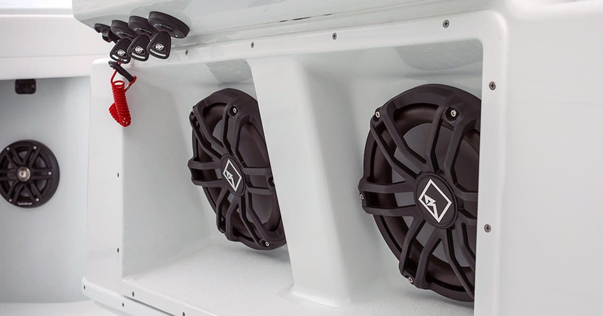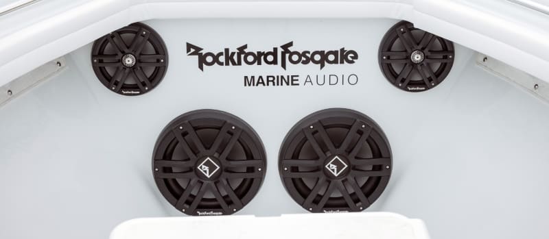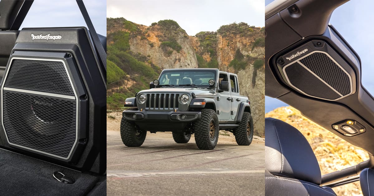
I remember when only one or two large car audio companies offered products designed specifically for marine applications. These days, there are dozens of brands in that market. From my extensive hands-on research, I can tell you that Rockford Fosgate is one of the brands you’ll want to check out for your boat. Their engineering-based marine speaker solutions are truly unique in the market. This Product Spotlight will examine the M2-Series M2-65 and M2-65B 6.5-inch Color Optix marine speakers.
Rockford Fosgate Marine Speaker Features
As is typical of Rockford Fosgate, they offer diverse speaker solutions to suit every application and budget. The Marine series starts with the affordable M0 line, which features white or black 6.5-inch coaxial drivers. From there, you step up to the M1 line, adding 6-, 6.5- and 8-inch drivers with Color Optix integrated RGB LED lighting. These speakers can handle even more power so that they can play louder. At the top of the marine speaker series are the M2 speakers. In this line, you have 6.5-, 8- and 10-inch coaxial drivers, with the two larger offerings available with a conventional tweeter or a small compression horn.
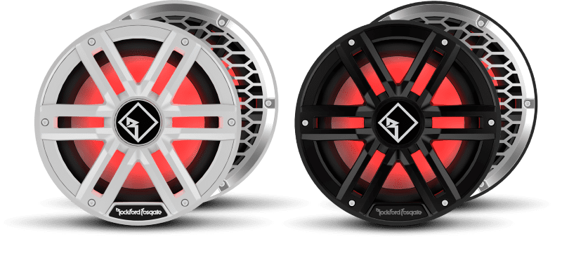
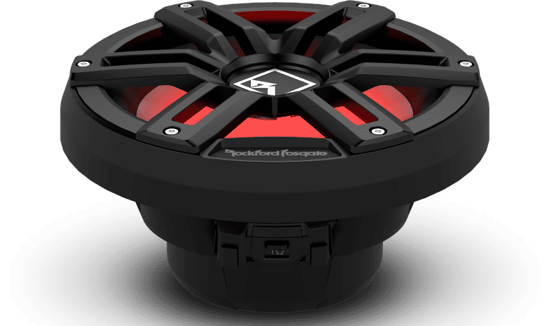
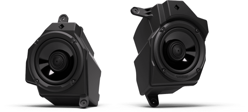
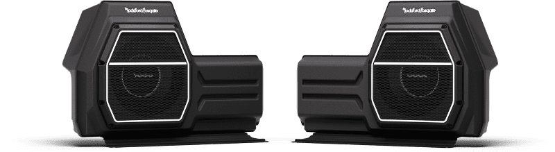
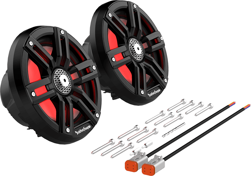
The M2-65 and M2-65B speakers are 6.5-inch coaxial drivers with your choice of white or black (the B at the end of the part number) grilles. The speaker system includes two drivers, stainless-steel grille inserts, mounting hardware and speaker wire pigtails with high-quality Deutsch connectors.
They are rated to handle 150 watts of power continuously with peaks of 300 watts. Efficiency is specified as 91.8 dB at 1 watt/1 meter. The drivers have a nominal impedance of 4 ohms and require 2.49 inches of mounting depth in a 5.36-inch cutout in your boat.
Marine Speaker Chassis Design
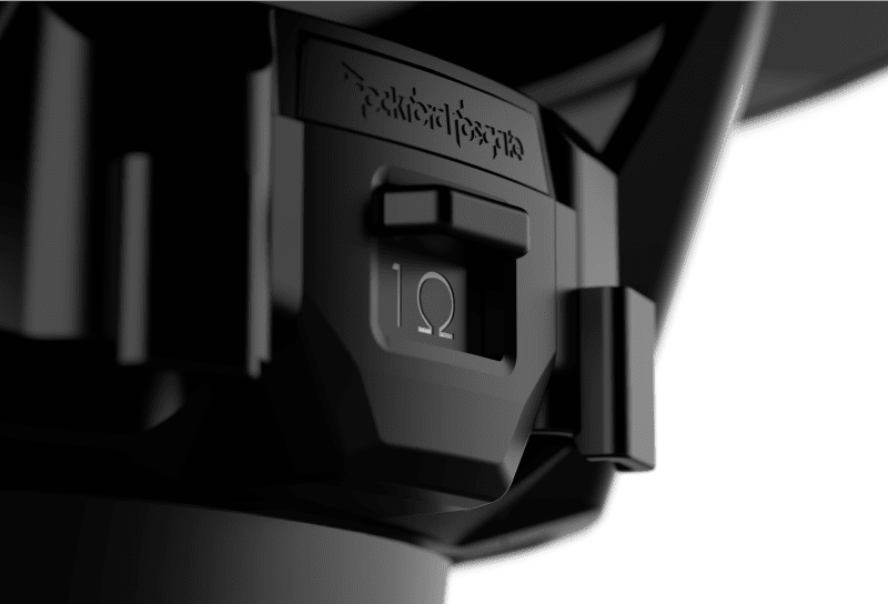
The woofer basket is injection molded from PA66 with UV inhibitors, a plastic mixture reinforced with 30% glass fiber for added thermal stability, damping and rigidity. As mentioned, electrical connections to the speaker are made via integrated Deutsch connector sockets.
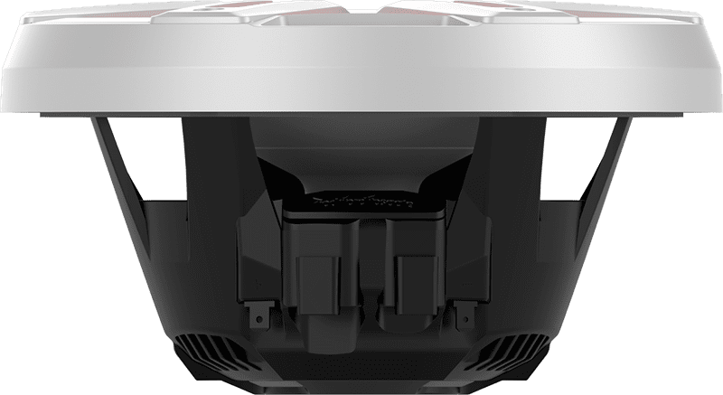
The speaker’s chassis includes cooling vents with a nano-coated mesh screen to help keep water out. The basket conceals a -12 dB/octave crossover for the tweeter. They call this their Integrated Concealed Crossover design.
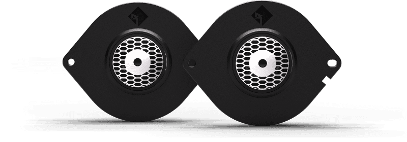
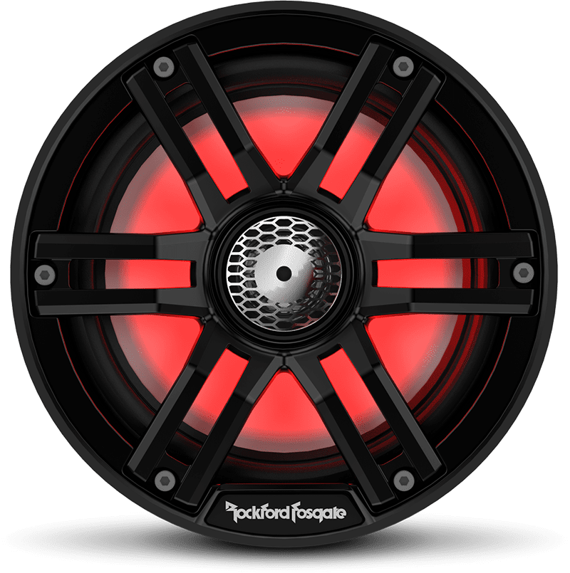
The speakers have a 12-spoke plastic grille made from ultraviolet- and salt-resistant Centrex plastic. As mentioned, the laser-cut stainless-steel inserts are also included in the package. Just let your installer know what look you want; they can take care of everything during installation.
Speaker Component Features
The mineral-filled polypropylene woofer cones feature a co-molded thermoplastic elastomer synthetic rubber surround. The surround uses the Vertical Attach Surround Technique mounting geometry where it attaches to the chassis. This feature increases cone area, which improves sensitivity and bass output. A 1-inch diameter, high-temperature Kapton voice coil former is at the base of the cone. The large diameter of the voice coil is the key reason these speakers are rated to handle 150 watts of power continuously. A linear aramid-polyester spider provides good cone control and high excursion levels. The tinsel leads, attached to gold-plated brass terminals in the chassis, are encased in rubber to protect them from water damage.
The 1-inch tweeter in the speaker’s center features a design that Rockford Fosgate calls PXNX. It uses a pair of compact neodymium slugs for excellent efficiency.
Color Optix RGB LED Lighting
A second four-pin socket on the speaker chassis provides access to the Color Optix RGB lighting. Your installer can power the lights using the Rockford Fosgate PMX-RGB LED lighting controller. The controller works with the RF Connect app on your smartphone to let you select the light color or illumination pattern. The RF Connect app is available for both Android and iOS mobile devices.
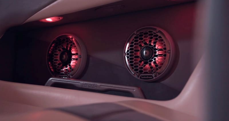
The LEDs are mounted to the underside of the grille. An optically clear, UV-stable coating protects the lighting from water damage. When on, the lighting makes the woofer cone glow in your choice of thousands of colors. You can also use the RF Connect app to select color-shifting patterns.
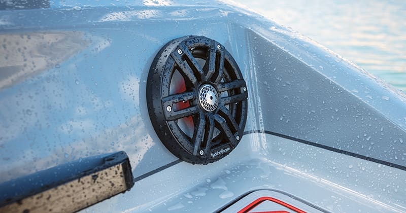
Element Ready Design Ensures Reliable Performance
Rockford Fosgate doesn’t pull any punches when it comes to ensuring that their marine audio products can withstand whatever Mother Nature throws their way. Their Element Ready design covers water resistance and UV and salt exposure. In terms of waterproofing, these speakers carry an IPX6 rating. Ultraviolet exposure testing passes the ASTM G154 500-hour accelerated UV test. Salt exposure is evaluated using the ASTM B117 500-hour salt-fog test. Finally, many marine and powersports speaker manufacturers overlook vibration and impact testing. Rockford Fosgate uses the ISO60068-2-64 Vibration testing standard to ensure that the speakers can take a beating as your boat hits even the gnarliest waves. Rockford Fosgate backs the M2 speakers with a two-year warranty against manufacturing defects.
Upgrade Your Boat with Rockford Fosgate M2-65 or M2-65B Speakers Today
If you’re shopping for high-performance marine speakers for your boat, drop by a local authorized Rockford Fosgate retailer today to audition the M2-65 and M2-65B speakers. They can design a marine entertainment system with a source unit, high-performance amplifiers, speakers and subwoofers so that your boat sounds the best on the lake or river. To find a retailer, use the locator tool on their website. For more information about Rockford Fosgate products, visit their website, Facebook page, Instagram feed or YouTube channel.
This article is written and produced by the team at www.BestCarAudio.com. Reproduction or use of any kind is prohibited without the express written permission of 1sixty8 media.