Imagine you are driving your side-by-side down a twisty, high-speed trail. You want to crank up the volume on your stereo. Do you take your hands off the wheel to make an adjustment? You don’t have to if you have the Rockford Fosgate PMX-BTUR universal remote control installed. Let’s check it out!
What is the Rockford Fosgate PMX-BTUR?
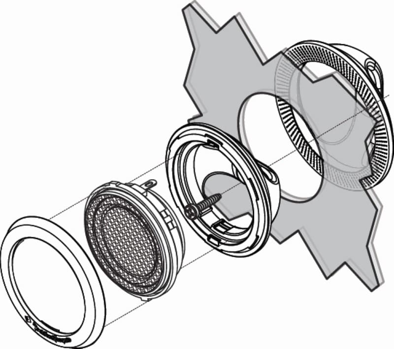
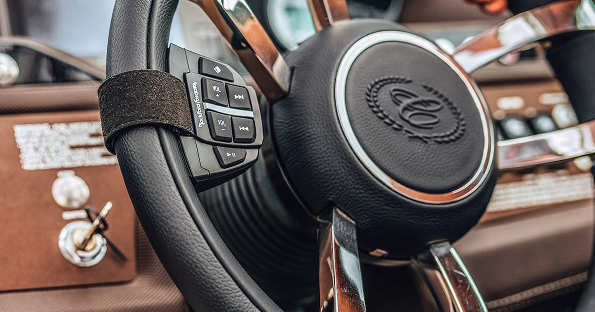
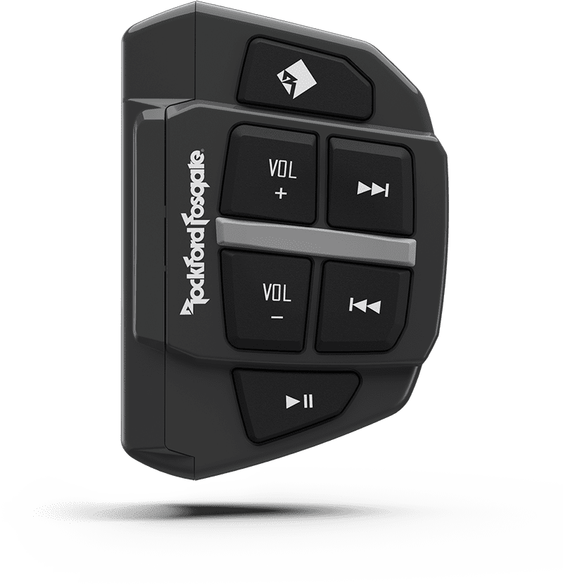
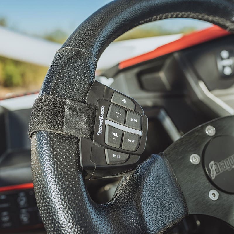
The PMX-BTUR is a remote designed to mount on the steering wheel of your side-by-side, boat, car, or truck. The remote pairs with your smartphone using Bluetooth and allows you to control the device. You can adjust the smartphone’s volume, change tracks, or even answer a phone call. When used with an iPhone, you can also fast-forward and pause what’s playing.
The remote is impressively compact, measuring only 2-3/4 inches tall, 1-7/8 inches wide, and 1-1/4 inches thick. Your installer can mount it on the dash or a center console using two-sided tape. The remote also comes with a heavy-duty Velcro strap and mounting adapter that allows it to be attached to the inside of your steering wheel. Best of all, there are no wires to run. The device is powered by an easily replaceable CR2032 coin cell.
How Does the PMX-BTUR Work?
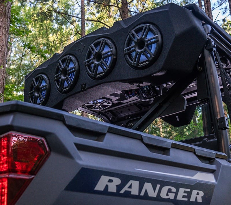
The PMX-BTUR is easy to configure and use. Once installed, press any button to wake the remote up. You can then search for PMX-BTUR in the list of available devices. Once selected, it will pair with your smartphone. The remote uses Bluetooth 4.0 to communicate commands to your phone. It uses Bluetooth Low Energy (BLE) as only small digital commands are transmitted back to the phone. This communication method dramatically reduces power consumption and extends the battery’s life. Low Energy Bluetooth still provides up to 30 feet (10 meters) of range. As such, you can use your Polaris Ranger’s Rear Audio Cap to provide music for the entire campsite and control it all with the PMX-BTUR.
Durable Design for Long Life
Rockford Fosgate knows how crazy things can get in a side-by-side or after an evening of hanging out with friends by the campfire. The PMX-BTUR remote is IP67 rated, so it can be dropped in the water or get dusty without fear of failing. The materials used to construct the remote are designed to withstand prolonged UV and salt spray exposure.
Remote Control Adds Safety
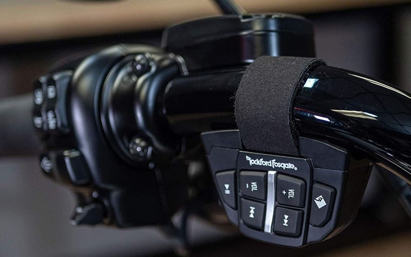
The PMX-BTUR controls the operation of your phone, not a radio. As such, you can pair your phone with almost any radio brand and use this remote. It would be an excellent solution for a factory-installed or aftermarket motorcycle audio system mounted on the handlebar. You could even use the PMX-BTUR with a motorcycle helmet and built-in speakers.
Of course, if you are captaining a boat, then the PMX-BTUR adds instant convenience. Imagine being at the helm of a jet boat headed up the rapids. Keeping your hands on the wheel is crucial to ending the day with great stories instead of drama. The PMX-BTUR is a perfect solution!
Do you have an older car or truck without steering-wheel audio system controls? The PMX-BTUR is the perfect solution for controlling your phone. Stream music from a service like Pandora or Spotify, then use the remote to change tracks or adjust the volume.
Add Audio System Convenience Today
If you’re looking for a remote that works with most smartphones to provide volume, track selection, and let you answer a call, drop by a local authorized Rockford Fosgate retailer today. You can find a shop near you using the online locator tool on their website. As always, be sure to follow our fanatical friends from Tempe on Facebook, Instagram, and, of course, YouTube.
This article is written and produced by the team at www.BestCarAudio.com. Reproduction or use of any kind is prohibited without the express written permission of 1sixty8 media.